
DIY Solar Simulator: Programmable Light Dimmer for Replicating Orbital Light/Dark Cycles
04 May 2025In the world of satellite engineering and research, understanding how components behave under the cyclical light and darkness conditions experienced in orbit is crucial. Professional testing equipment can be prohibitively expensive, but with some basic electronics knowledge, we can build a DIY solution that simulates these conditions remarkably well.
This project represents the latest addition to our laboratory’s integrated research ecosystem, complementing our previous work on the Perovskino MPPT tracker for solar cell characterization. As our team continues exploring novel photobattery systems that combine energy harvesting and storage in unified devices, accurately simulating the unique light/dark cycles experienced in different orbital environments has become essential for testing these emerging technologies under realistic space conditions.
In this post, I’ll share how I built a programmable light dimmer specifically designed to replicate the light/dark cycles experienced by satellites in various orbits using a halogen dichroic lamp.
The Problem: Simulating Satellite Light Conditions
Satellites in different orbits experience varying patterns of light and darkness. For example, the International Space Station in Low Earth Orbit (LEO) experiences approximately 16 cycles of day and night every 24 hours, with roughly 55 minutes of sunlight followed by 35 minutes of darkness in each 90-minute orbit. Satellites in higher orbits have different patterns - some in special sun-synchronous orbits might even experience constant sunlight.
Testing how solar panels, sensors, and other components respond to these lighting patterns is essential for satellite development, but commercial solar simulators are expensive. This is where our DIY solution comes in.
The Solution: A Programmable Light Dimmer
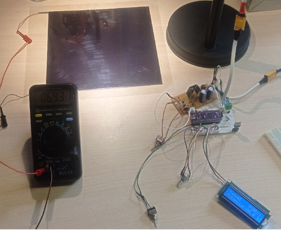 Figure: The light dimmer, unboxed components
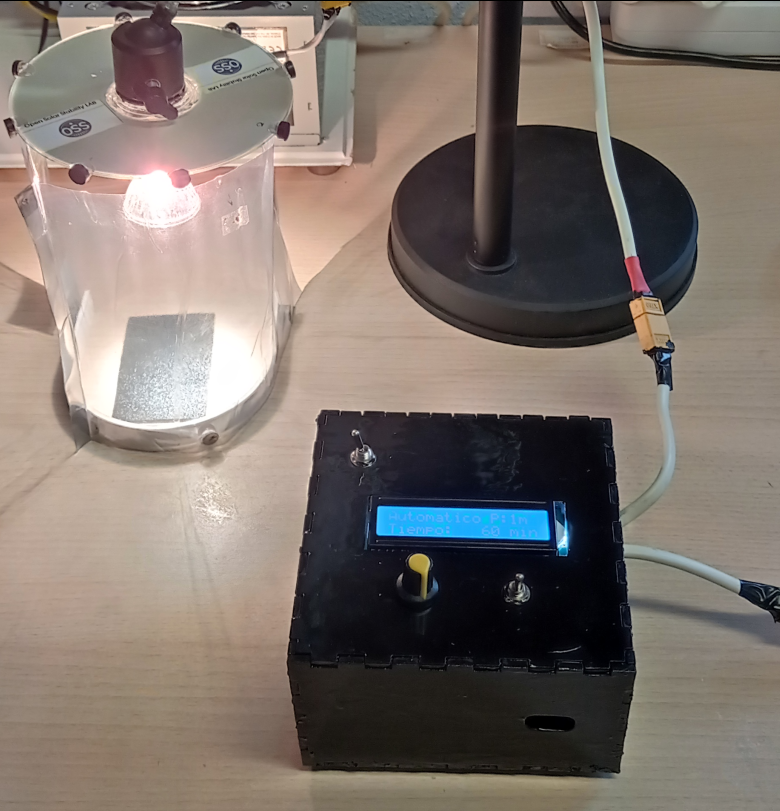 Figure: The light dimmer in a box
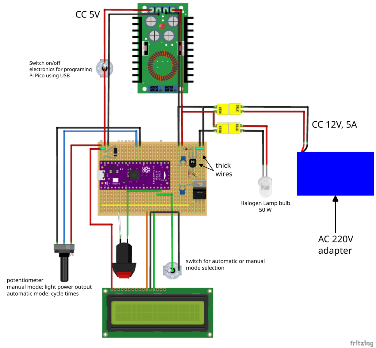
Our system consists of a Raspberry Pi Pico microcontroller-based dimmer circuit that can control the power output of a halogen dichroic lamp to simulate different lighting patterns. The key features include:
- Dual operation modes: Manual power selection or programmable automatic cycles
- Pattern flexibility: Support for both sinusoidal transitions (smooth changes) and linear ramps
- Complete cycle control: Programmable light intensity and duration of light/dark phases.
- Real-time monitoring: LCD display showing current status and parameters
- Data acquisition: Light power calibration and voltage/current measurement of solar cells for power analysis using our Perovskino MPPT tracker
Hardware Components
The project uses:
- A microcontroller (Raspberry Pi Pico shown in the diagram)
- LCD display for user interface
- Potentiometer and button for user control (alternatively using a pulsable rotary encoder)
- Various basic electronic components (resistors, capacitors, diode, N-mosfet and npn-transistor)
- Halogen dichroic lamp (50 W) as the light source
- AC adapter and linear voltage regulator to feed lamp and electronics.
How It Works
The system is controlled by a Raspberry Pi Pico running MicroPython code that handles two main modes of operation:
Manual Mode
In manual mode, a potentiometer directly controls the brightness of the halogen lamp. The system reads the analog input, applies a moving median filter to reduce noise, and maps this value to the appropriate power level using a calibrated lookup table. This ensures accurate and consistent brightness control.
The LCD display shows:
- Raw ADC value from the potentiometer (0-65535)
- Limited ADC value (within operational thresholds)
- Calculated power percentage (0-100%)
Automatic Mode
In automatic mode, the system runs programmable light/dark cycles to simulate satellite orbit conditions:
-
Setup Phase: The potentiometer sets the light/dark cycle time (up to 12 hours), displayed on the LCD in minutes.
-
Execution Phase: Once started with a button press, the system automatically transitions between light and dark phases:
During the light phase, two transition patterns are available:
- Sinusoidal transition: Uses sine wave functions for smooth, gradual transitions (more natural)
- Linear ramp transition: Uses linear functions for constant rate of change
The LCD display during execution shows:
- Current power percentage
- Elapsed time in the cycle
- Remaining time in the cycle
Power Calibration System
One of the most innovative aspects of this system is its power calibration method. Instead of using a simple linear relationship between PWM duty cycle and perceived brightness (which would result in inaccurate power control), the system uses:
- A calibrated lookup table that maps desired power percentages to precise ADC values
- Mathematical models that account for the non-linear relationship between electrical power and perceived brightness
- Adaptive update intervals that scale based on cycle duration to maintain smooth transitions while preserving CPU resources
This approach ensures that the simulator can accurately reproduce the precise light conditions experienced by satellites in different orbits, making it an effective tool for testing solar panels, sensors, and other light-sensitive components under realistic space conditions.
Power Output Patterns & Transition Types
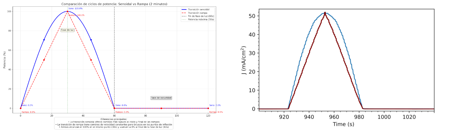
The graphs above show both the theoretical design patterns (left) and the actual measured light power trace (right) of the system demonstrating how the system produces controlled light patterns with precise timing.
The system supports two primary types of light transitions:
- Sinusoidal transition (blue line): Provides smoother power changes at the beginning and end of the ramp, which may better simulate natural light transitions
- Linear ramp (red line): Offers constant rate of change, which may be preferred for certain testing scenarios
but other programable transitions as pulse lights or ramp and dewelling stages are also posible.
As shown in the comparison graph, both patterns achieve the same maximum power (100%) and return to 0% at the end of the primary light phase, but their transition characteristics differ significantly between simple linear ramps or sinuosuodial pattern.
Applications for Satellite Testing
This DIY solar simulator is particularly useful for testing:
- Solar panel performance under different orbital illumination patterns
- Power management systems that need to handle cyclical charging and discharging stages
- Photobattery integration
- Optical sensors and cameras that must operate in varying light conditions
- Thermal cycling effects caused by repeated heating and cooling
By programming different light/dark cycles, we can simulate various orbital characteristics:
- LEO satellites (like the ISS): ~90-minute orbits with ~60 minutes of light and ~30 minutes of darkness
- Medium Earth Orbit satellites: Longer cycles with different light/dark ratios
- Geostationary satellites: 24-hour cycles with seasonal variations in eclipse time
- Sun-synchronous orbits: Nearly constant illumination with brief shadow periods
Conclusion
This relatively simple DIY project provides a powerful tool for simulating the light conditions experienced by satellites in various orbits. Whether you’re a hobbyist working on a CubeSat project, a student doing research, or simply curious about satellite conditions, this programmable light dimmer offers an affordable way to replicate space lighting patterns.
The system’s flexibility means it can be easily adapted to simulate specific satellite orbits or testing scenarios. The ability to choose between sinusoidal and linear transitions also allows for more nuanced testing of how components respond to different rates of illumination change.
Have you built similar testing equipment for space-related projects? I’d love to hear about your experiences!
Note: This project involves working with AC line voltage, which can be dangerous. Always take appropriate safety precautions when building and using high-voltage electronic devices.